The content of this category identifies all 7-Bar and 3-Bar ECM currently approved by the DDESB for new construction. Notes are provided to identify those ECM that have NEW limitations and/or restrictions associated with their approval.
Select a drawing number to view and download files associated with that ECM.
These documents are available in the following formats: Adobe Acrobat (PDF) | CAD in compressed ZIP | DWG
Description | Drawing Number | Dimensions | Door Opening | Weight |
|---|---|---|---|---|
Type G Box ECM Standard Drawings | 14145654 through 14145739 | 94'-8" Wide x 50'-0" Long x 14'-9.75" (Rear) To 15'-10" (Front) High | (3) Sliding 26'-0" Wide x 11'-0" High | 500,000lb |
Approved Files for UseDocumentationComments/Design ConsiderationThe Type G Box ECM has been designed for the storage of munitions. The design of this structure was based on the design of the existing Navy Type C Box ECM, updated to comply with current design criteria, address operational issues noted in previous designs, and improve overall ability to support the Navy explosive storage needs moving forward. Due to the comprehensive nature of the updates to the Type C Box magazine, it has been completely redesigned and renamed the Type G Box magazine. The interior horizontal dimensions of the Type G are the same as the Type C. The clear height, from floor to ceiling, at the front interior space is the same as the Type C, however the roof slope was decreased which increases the clear height, from floor to ceiling, at the rear of the interior space. The columns and door openings have been shifted slightly to promote symmetry, ease of construction, and better efficiency. The exterior walls are thicker, and a mat slab design was used for the foundation. Mechanical rooms were included as site adapt options. The pilasters and header beams have been reconfigured to better absorb and dissipate blast hazards in a detonation scenario, and the blast door includes enhanced physical security features, an automated trench plate lifting system, and a bottom-supported wheel and rail system. 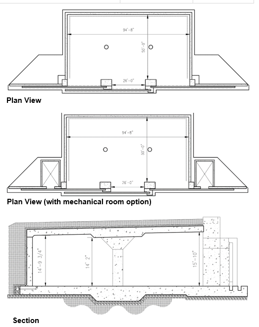 | ||||
Type H Box ECM Standard Drawings | 14138777 through 14138861 | 158'-8" Wide x 50'-0" Long x 14'-9.75" (Rear) To 15'-10" (Front) High | (5) Sliding 26'-0" Wide x 11'-0" High | 500,000lb |
Approved Files for UseDigital DrawingsDocumentationComments/Design ConsiderationThe Type H Box ECM has been designed for the storage of munitions. The design of this structure was based on the design of the existing Navy Type D Box ECM, updated to comply with current design criteria, address operational issues noted in previous designs, and improve overall ability to support the Navy explosive storage needs moving forward. Due to the comprehensive nature of the updates to the Type D Box magazine, it has been completely redesigned and renamed the Type H Box magazine. The interior horizontal dimensions of the Type H are the same as the Type D. The clear height, from floor to ceiling, at the front interior space is the same as the Type D, however the roof slope was decreased which increases the clear height, from floor to ceiling, at the rear of the interior space. The columns and door openings have been shifted slightly to promote symmetry, ease of construction, and better efficiency. The exterior walls are thicker, and a mat slab design was used for the foundation. Mechanical rooms were included as site adapt options. The pilasters and header beams have been reconfigured to better absorb and dissipate blast hazards in a detonation scenario, and the blast door includes enhanced physical security features, an automated trench plate lifting system, and a bottom-supported wheel and rail system. 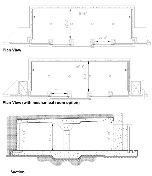 | ||||
Single Bay CLWS Navy ECM Standard Drawings | 12905820 through 12905870 | 119'-0" Long x 32'-0" Wide | 32'-0" Wide x 14'-0" High | 500,000lb |
Approved Files for UseComments/Design ConsiderationThese drawings represent the single bay configuration of the Containerized Long Weapons Storage (CLWS) Navy Earth Covered Magazines, approved by DDESB on 25 July 2024. All new construction of single bay CLWS Magazines will be in accordance with drawings 12905820 through 12905870. The Single Bay CLWS ECM is a cast-in-place reinforced concrete box magazine 32 ft-wide. The magazine can be built 95'-6" or 119' long and has a minimum interior height of 24'-8", with a transverse roof slope of 1/4" per foot. The roof, side and rear walls, and headwall of the magazine consist of 24" thick concrete walls. The blast door of the magazine consists of a single sliding steel door, spanning vertically between a bottom trench and a header beam, covering a 14-ft tall, 32-ft wide opening. This header beam frames into pilasters located at the intersection of the headwall and sidewalls. The blast door includes enhanced physical security features, an automated trench plate lifting system, and a bottom-supported wheel and rail system. | ||||
Double Bay CLWS Navy ECM Standard Drawings | 12914696 through 12914757 | 114'-0" Long x 50'-0" Wide x (minimum) 24'-7 1/2" high | 32'-0" Wide x 14'-0" High | 500,000lb |
Approved Files for UseComments/Design ConsiderationThese drawings represent the double bay configuration of the Containerized Long Weapons Storage (CLWS) Navy Earth Covered Magazines, approved by DDESB on 26 January 2025. All new construction of double bay CLWS Magazines will be in accordance with drawings 12914696 through 12914757. The Double Bay CLWS ECM is a novel reinforced concrete box-type design with two bays separated by an interior reinforced concrete wall. Each bay has clear interior dimensions of 114'-0" length by 50-'0" width by minimum 24'-7 1/2" height. The front wall of each bay has a door opening with clear dimensions of 32'-0" width by 14'-0" height. The design also includes optional interior bridge crane and two mechanical rooms for environmental controls. | ||||
Navy Modular Storage Magazine Version 2 | 14148449 through 14148533 | 25'-0" Wide x 81'-6" Long x 14'-8" High | (1) Sliding | 500,000lb |
Approved Files for UseComments/Design ConsiderationThese drawings represent the new design of Navy Modular Storage Magazine (MSM) Version 2, approved by DDESB on 28 April 2025. All new construction of MSMs will be in accordance with drawings 14148449 through 14148533. | ||||
Navy Modular Storage Magazine | ||||
RC Box Type 'M' | ||||
RC Box Type 'C' | ||||
RC Box Type 'D' | ||||
RC Circular Arch | ||||
Composite Circular Arch | ||||
Composite Oval Arch | ||||
RC Box Type 'E' | ||||
RC FRELOC Stradley | (Korean Version) | 25'-0" Wide x 87'-0" Max. Length (normally length is 60' or 80') x 13'-0" (Rear) High | (1) Sliding | 500,000lb |
Approved Files for UseComments/Design ConsiderationThis design is the latest approved version of the Republic of Korea Army (ROKA) drawing for 33-15-74. The original basis for the Korean version was U.S. Army COE 33-1-74. The Korean drawings assure that all reinforcing steel is electrically continuous. The previous version of this drawing was approved by the DDESB as a 7-bar magazine on 25 May 2002.  | ||||
RC FRELOC Stradley | (Modified Korean Version) | 25'-0" Wide x 87'-6" Max. Length (normally length is 60' or 80') x 13'-0" (Rear) High | (1) Sliding | 500,000lb |
Approved Files for UseComments/Design ConsiderationThis design is a modified version of the Republic of Korea Army (ROKA) drawing for 33-15-74. The original basis was U.S. Army COE 33-1-74. The Korean drawings assure that all reinforcing steel is electrically continuous. The Modified version includes provisions for air conditioning the magazine. The original version of this drawing was approved by the DDESB as a 7-bar magazine on 25 May 2002.  | ||||
Steel, Semi-Circular Arch | 421-80-01 | Approx. 26'-0" Wide x 19'-0" Min. expandable up to most commonly used 89'-0" Length x 14'-0" (Max.) High | (1) Sliding | 500,000lb |
Approved Files for UseNone at this time. Comments/Design ConsiderationUnder Army Review, Not Approved for New Construction If a steel arch ECM is required, use standard drawings 421-80-03, Steel Oval Arch. Contact HNC and USATCES for additional guidance on appropriate site adapt of the 421-80-03 standard.  | ||||
Steel Oval Arch | 421-80-03 | 28'-2" (Max.) Wide x 21'-0" Min. to 89'-0" Max. Length x 14'-11" (Max.) High | (1) Sliding | 500,000lb |
Approved Files for UseComments/Design ConsiderationReplaced 33-15-73. Arch design composed of a 1-gauge (0.280 inch) corrugated steel arch. The site-adapt Designer of Record shall ensure DoD and Army explosives safety requirements for Lightning Protection and Grounding are met. The Designer of Record shall obtain review support and technical concurrence of the site-adapt design from the U.S. Army Corps of Engineers Engineering and Support Center, Huntsville.  | ||||
RC Arch | 421-80-05 | 26'-7 1/4" Wide x 90'-0" Max. Length (normally length is 60' or 80') x 14'-0" (Rear) High | (1) Sliding | 500,000lb |
Approved Files for UseDigital Drawings
DocumentationComments/Design ConsiderationConstructed using the Techspan Precast Concrete System, developed by the Reinforced Earth Company, for each construction. The headwall and door are derived for 33-15-74.  | ||||
RC Box | 421-80-07 | 25'-0" Wide x 20'-0" Min. to 80'-0" Max. Length x 11'-0" High | Hinged | 500,000lb |
Approved Files for UseDigital Drawings
DocumentationComments/Design ConsiderationMSM Standard 421-80-07 replaces the previous MSM Standard 421-80-06 (modified). The new series updates the drawings to meet current AEC CAD standards, improved plan readability, constructability, and correct omissions within the construction drawings. Another key element performed during the revision was the incorporation of lessons learned from previous MSM projects at various user organizations. In addition to the drawings, a conventional structural load analysis was performed to identify some key loading limits, which will assist the designer during the site-adaption process.  | ||||
Modular Storage Magazine, Box-Type | 421-80-08 | 25'-0" Wide x 20'-0" Min. to 80'-0" Max. Length x 14'-8" High | Hinged | 500,000lb |
Approved Files for UseDigital Drawings
DocumentationComments/Design ConsiderationThe MSM Box-Type Standard 421-80-08 replaces the previous Munitions Storage Magazine (14 feet ceiling height) as designed for Hill AFB. The new series updates the drawings to meet current AEC CAD standards, and features improved plan readability, constructability, and corrects omissions within the construction drawings. Another key element performed during the revision was the incorporation of lessons learned (see Appendix of Design Narrative) from previous MSM projects at various user organizations. In addition to the drawings, a conventional structural load analysis was performed to identify some key loading limits, which will assist the designer during the site-adaption process.  | ||||
ECM, Concrete Oval-Arch | 421-80-09 | 25'-0" Wide x 90'-0" Max. Length (normally length is 60' or 80') x 14'-0" (Rear) High | (1) Sliding | 500,000lb |
4Approved Files for UseDigital Drawings
DocumentationComments/Design ConsiderationCOE Standard 421-80-09 replaces the previous COE Standard 33-15-74. The new series updates the drawings to meet current AEC CAD standards, improves plan readability, constructability, and corrects omissions within the construction drawings. Headwall components have been re-analyzed under the 7-bar blast loading from DoD 6055.09-M using the methodology of UFC 3-340-02. The remaining components are as originally designed. In addition to the drawings, a conventional structural load analysis was performed to identify some key loading limits, which will assist the designer during the site-adaption process and a new retaining wall design was completed to simplify construction of the wing walls. The documentation will not include specifications.  | ||||
USACE Modular Storage Magazine Box–Type Flow–Thru | 421-80-10 | (internal): x 4470mm High | (2) Hinged | 500,000lb |
Approved Files for Use | ||||
USACE Modular Storage Magazine Box–Type European Version | 421-80-13 | (internal): x 4470mm High | (1) Sliding | 500,000lb |
Approved Files for Use | ||||
RC Box Type 'D' | 6448555 through 6448588 | 158'-8" Wide x 50'-0" Long x 13'-8" (Rear) To 15'-10" (Front) High | (3) Sliding | 500,000lb |
Approved Files for UseComments/Design ConsiderationUnder Navy Review. Contact NAVFAC LANT, Code CI42 This design is identical to NAVFAC 6448522 through 6448554, Box Type D, except that it incorporates a High Security Integrated Locking System (HSILS).  | ||||
RC Box Type 'F' | ||||
RC Box | Munitionslagerhause | |||
Steel Oval Arch | Munitionslagerhause | |||
RC Box | Munitionslagerhause | |||
Steel Oval Arch | Munitionslagerhause | |||